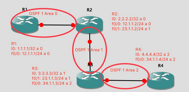
拓扑如下图所示:

如上图所示,R1和R2相接为Area0,R2和R3相接为Area1,R3和R4相接为Area2。由于Area2与Area0直接隔着一个非骨干区域(Area1),无法相互传递路由信息,因此需要在R2和R3之间通过虚链路技术搭建一条逻辑通道,使两台ABR(区域边界路由器)之间可以直接传递路由信息(3类LSA)。具体配置如下:
R2:

interface Loopback0

ip address 2.2.2.2 255.255.255.255

exit

interface FastEthernet0/0

ip address 12.1.1.2 255.255.255.0

no sh

exit

interface FastEthernet0/1

ip address 23.1.1.2 255.255.255.0

no sh

exit

router ospf 1

router-id 2.2.2.2

area 1 virtual-link 3.3.3.3 //在R2和R3(ABR)之间,建立一条逻辑的连接通道

network 2.2.2.2 0.0.0.0 area 1

network 12.1.1.0 0.0.0.255 area 0

network 23.1.1.0 0.0.0.255 area 1

R3:

interface Loopback0

ip address 3.3.3.3 255.255.255.255

exit

interface FastEthernet0/0

ip address 34.1.1.3 255.255.255.0

no sh

exit

interface FastEthernet0/1

ip address 23.1.1.3 255.255.255.0

no sh

exit

router ospf 1

router-id 3.3.3.3

area 1 virtual-link 2.2.2.2

network 3.3.3.3 0.0.0.0 area 1

network 23.1.1.0 0.0.0.255 area 1

network 34.1.1.0 0.0.0.255 area 2